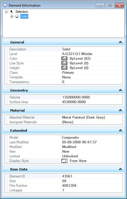
| Element list box |
Lists the selected elements. To review one of multiple selected elements, you must first select the list entry for that element. Expand the tree to display the element you selected. |
| General |
Displays general properties of the selected element, active model, or open DGN file.
|
| Geometry |
Displays geometric properties of the selected element.
| Affinity |
| Angle |
| Area — Determines whether a closed element is a solid or a hole. |
| Active Z depth |
| Aspect Ratio |
| Axis Ratio |
| Back Crop |
| Back Depth |
| Background Color |
| Bottom Crop |
| Bottom Height |
| Boundary Data |
| Boundary Edge Count |
| Camera Position |
| Center |
| Center 1 |
| Center 2 |
| Clip Origin |
| Clip Width |
| Closed |
| Control Net |
| Control Point Data |
| Control Point Data > Physically Closed |
| Control Point Data > Row Count |
| Control Point Data > Column Count |
| Control Point Data > Row Index |
| Control Point Data > Column Index |
| Control Point Data > Control Point Count |
| Control Point Data > Row Size |
| Control Point Data > Column Size |
| Control Point Data > Control Points |
| Control Point Data > Control Points > Point |
| Control Point Data > Control Points > Weight |
| Control Point Data > Weights |
| Control Point Data > Weights > Point |
| Control Point Data > Weights > Weight |
| Control Polygon |
| Count |
| Delta X |
| Delta Y |
| Delta Z |
| Dimension |
| Direction |
| Directional Vectors |
| DPI |
| Edge Count |
| Elevation |
| Elevation Angle |
| End |
| End Angle |
| End Data Point |
| End Data Point > Point |
| End Data Point > Tangent Method |
| End Data Point > Tangent Source |
| End Data Point > Tangent |
| End Point |
| Extents |
| Face Count |
| Face Data |
| Fit Point Data |
| Fit Point Data > Physically Closed |
| Fit Point Data > Fit Point Count |
| Fit Point Data > Fit Points |
| Front Crop |
| Front Depth |
| Geocoding |
| GeoPriority |
| Hidden Edge Count |
| Interior Edge Count |
| Knot Data |
| Knot Data > Uniform |
| Knot Data > Knot Count |
| Knot Data > Knots |
| Knot Data > Knot, Multiplicity > Value |
| Knot Data > Knot, Multiplicity > Multiplicity |
| Left Crop |
| Length |
| Normal |
| Number of Pixels |
| Order |
| Orientation |
| Origin |
| Perimeter |
| Periodic |
| Pixel Size |
| Planar |
| Planar Distance |
| Preserve Up |
| Primary Axis |
| Primary Vector |
| Radius 1 |
| Radius 2 |
| Rational |
| Right Crop |
| Rotation |
| Rotation X |
| Rotation Y |
| Rotation Z |
| Scale |
| Scale X |
| Scale Y |
| Scale Z |
| Secondary Axis |
| Secondary Vector |
| Segments |
| Start |
| Start Angle |
| Start Data Point |
| Start Data Point > Point |
| Start Data Point > Tangent Method |
| Start Data Point > Tangent Source |
| Start Data Point > Tangent |
| Start Point |
| Surface Area |
| Sweep Angle |
| Top Height |
| Total Elevation |
| Total Length |
| Top Crop |
| U Data |
| User Origin |
| V Data |
| View Index |
| Vertex Count |
| Vertex Data |
| Volume |
|
| Material |
Displays material properties of the selected element.
| Face Attachments |
| Assigned Materials |
| Attached Material |
|
| Extended |
Displays extended properties of the selected element.
| End Cap |
| Joints |
| Last Modified |
| Line Style Parameters |
| Line Style Parameters > Scale |
| Line Style Parameters > Width Mode |
| Line Style Parameters > Start Width |
| Line Style Parameters > End Width |
| Line Style Parameters > Constant Width |
| Line Style Parameters > True Width |
| Line Style Parameters > Shift Mode |
| Line Style Parameters > Shift |
| Line Style Parameters > Fraction Phase |
| Line Style Parameters > Corner Mode |
| Locked |
| Model |
| Modified |
| New |
| Profile Count |
| Profiles |
| Snappable |
| Solid |
| Start Cap |
| Thickness — Gives thickness to planar elements. If the value is positive, the thickness is applied in the positive Z (global) direction and if it is negative the thickness is applied in the negative Z direction. By default, the thickness value is zero. The native element type remains same even after applying the thickness. The thickness property can be used to visualize a planar element in a view window other than the one in which it was drawn, by giving a non-zero thickness value. |
| View Dependent |
|
| Family & Part |
Displays the settings for the family and parts.
| Width |
| Height |
| Part |
| Family |
| File name |
| Level name |
| Element ID |
|
| Quantification |
Displays quantification properties of the selected element.
| Left Length |
| Center Length |
| Right Length |
| Left Area (Gross) |
| Right Area (Gross) |
| Left Area (Net) |
| Right Area (Net) |
| Volume (Gross) |
| Volume (Net) |
|
| Raw Data |
Displays raw data properties of the selected element.
| Element ID |
| File Position |
| Is Range Dynamic |
| Is Range Low |
| Linkages |
| Range High |
| Size |
| XAttributes |
|
| Formatting |
Displays text format-specific properties of the selected element.
| Is Annotation |
| Justification |
| Line Spacing |
| Line Spacing Type |
| Origin |
| Slant Angle |
| User Origin |
| Vertical |
| Width |
|
| Contents |
Displays text-specific properties of the selected element.
| Text String |
| Text Style |
| Vertical |
|
| Links |
Displays the names of the Project Explorer links attached to the selected element.
| Links — Clicking the button to the right of a link's name opens the Properties dialog, which lists the properties of the selected link. |
|
| Image |
Displays image-specific properties of the selected element.
| Color Mode |
| Compression |
| Description |
| File Size |
| Format |
| Logical Name |
| Read-Only |
|
| Color |
Displays color-specific properties of the selected element.
| Brightness |
| Contrast |
| Invert |
| Tint |
| Transparency |
|
| Display Print |
Displays printing and display properties associated with the selected element.
| Clip |
| Display Gamma |
| Layers |
| Plane |
| Print |
| Print Gamma |
| Raster Rotation |
| Views |
|
| Pattern Parameters |
Displays pattern-specific properties of the selected element.
| Angle |
| Associative |
| Origin |
| Pattern Definition |
| Scale |
|
| Groups |
Displays grouping properties associated with the selected element.
|
| Attachments |
Displays the attachment properties associated with the selected element.
| Angle |
| Description |
| Display |
| Display Raster Refs |
| File Name |
| Locate |
| Logical Name |
| Model |
| Offset |
| Orientation |
| Scale |
| Scale Line Styles |
| Snap |
| Transparency |
| Use Lights |
|